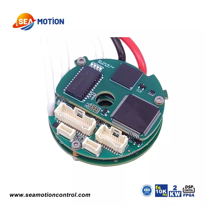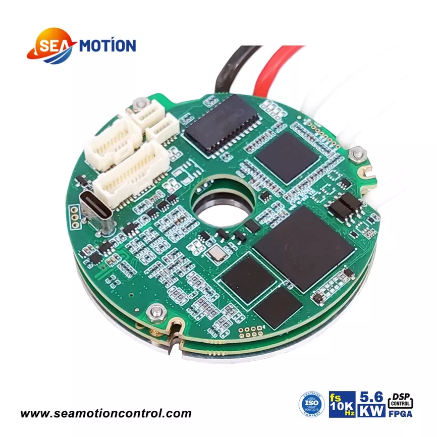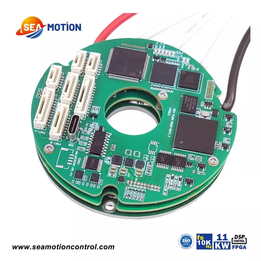
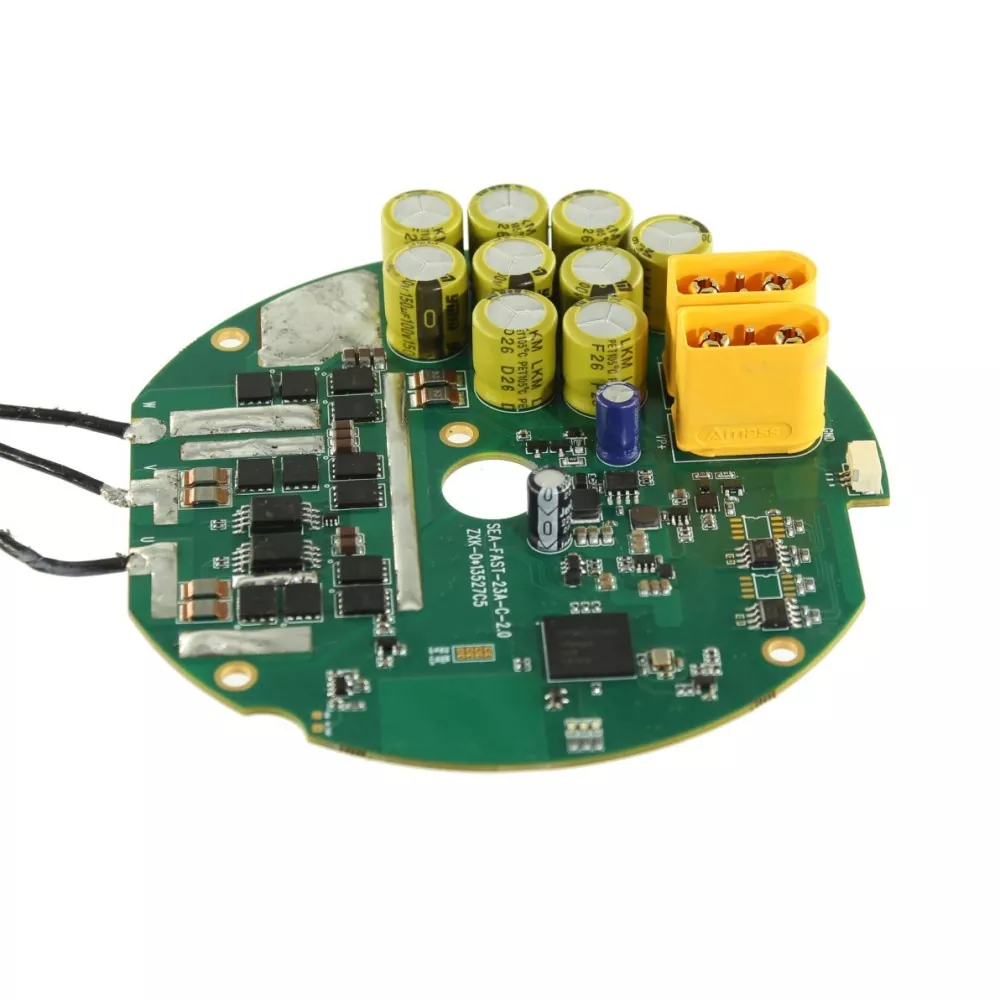
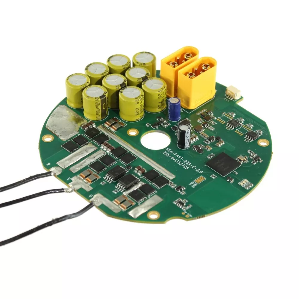
A frameless torque motor servo drive has to disappear inside the joint it controls. The SEA-C116 is a ring-shaped PCB that bolts to the rear of a joint housing, wraps around the motor shaft through a Φ15 mm centre bore, and leaves the axial space that a boxed drive would eat. Nothing hangs off the arm.
Power density is the reason the format exists. A 3.0 mm FR-4 board on a 72 VDC bus carries 23 A continuous and 110 A peak, using a three-phase full bridge with precision phase current sampling. Control is vector control with MTPA and field weakening, so the same drive holds torque at low speed and keeps control margin at the top of the speed range.
Feedback is where most joint drives fall short. The SEA-C116 takes two BiSS-C encoders at once — one on the motor shaft, one on the reducer output shaft — and closes the loop on both. Backlash and compliance in the reducer stop being a hidden error, because the drive reads the load side directly.
|
Item |
Specification |
|
Model |
SEA-C116-110-100-CAN+RS485-Dual BiSS-X |
|
Form factor |
Ring-shaped PCB, embedded in joint housing |
|
Outer diameter |
Φ116 mm |
|
Centre bore |
Φ15 mm |
|
Board thickness |
3.0 mm |
|
PCB material |
FR-4, double-sided assembly |
|
Mounting |
4 × Φ3.0 through holes, screwed to joint rear |
|
Supply voltage |
72 VDC (typical) |
|
Maximum bus voltage |
100 V |
|
Rated current |
23 A |
|
Peak current |
110 A |
|
Feedback |
Dual BiSS-C encoder, channel A + channel B |
|
Communication |
CAN 2.0 + RS485 |
|
Control algorithm |
Vector control (FOC), MTPA + field weakening |
|
Control modes |
Position / Velocity / Torque / MIT hybrid |
|
Power stage |
Three-phase full bridge, precision phase current sampling |
|
Protection |
Over-current, over-voltage, under-voltage, over-temperature, short circuit, encoder fault, CAN fault |
|
Brake |
None |
|
Digital IO |
None, control over bus |
|
Operating modes |
External control, standalone programmable, distributed network |
SEA - C116 - 110 - 100 - CAN+RS485 - Dual BiSS - X
|
Segment |
Meaning |
This model |
|
1 |
Brand code |
SEA |
|
2 |
Form factor, C = ring PCB, digits = outer diameter |
C116 = Φ116 mm |
|
3 |
Peak current, A |
110 A |
|
4 |
Maximum bus voltage, V |
100 V |
|
5 |
Communication interface |
CAN + RS485 |
|
6 |
Encoder type |
Dual BiSS-C |
|
7 |
X = non-resolver encoder, R = resolver |
X |
Other current, voltage, communication and feedback combinations are built to order against the same ring format. Send the joint envelope and the bus voltage, and the model code follows from it.
● Ring PCB, Φ116 mm outer diameter, Φ15 mm bore, 3.0 mm thick, embeds directly in the joint housing
● 72 VDC typical bus, 100 V maximum, matching common robot joint supplies
● 23 A continuous and 110 A peak, enough torque headroom for acceleration and impact
● Dual BiSS-C feedback on motor shaft and reducer shaft, full closed loop on both
● Vector control with MTPA and field weakening for efficiency across the speed range
● Position, velocity, torque and MIT hybrid control modes on one drive
● CAN 2.0 and RS485 on board, one cable harness for power and network
● Over-current, over-voltage, under-voltage, over-temperature, short circuit, encoder and CAN fault protection
● Single supply, minimal external wiring, no separate logic rail
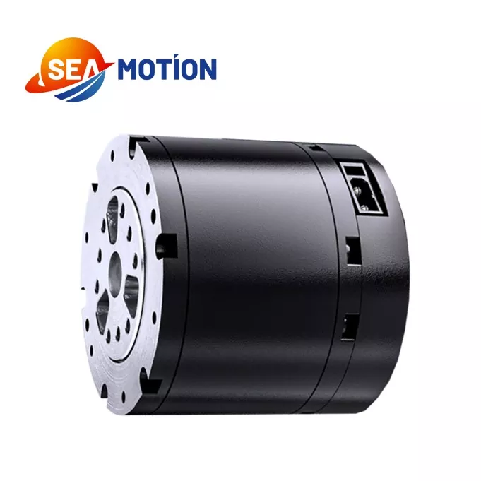
A frameless torque motor servo drive is only as good as the joint it fits into. The SEA-C116 is specified for collaborative robot arms, quadruped, biped and wheeled bionic robots, exoskeletons and assistive wearable devices, precision rotary tables, and general automation equipment where the drive has to sit inside the moving structure rather than in a cabinet.
The bus capacitor bank is the first thing you notice on the board, and it is deliberate: a ring of 160 V electrolytics sits on the DC bus close to the bridge, so the current loop sees a stiff rail during acceleration and regenerative braking instead of a sagging one. That is what makes 110 A peak credible on a 3.0 mm board.
The power stage runs a three-phase full bridge with precision phase current sampling on every leg. Current sensing quality is the ceiling on torque linearity, so this is where the cost sits.
The dual encoder front end is separate from the power section, with its own 5 V supply and ground return per channel, so encoder noise does not ride on the current loop. Channel A takes the motor shaft encoder, channel B the reducer shaft encoder; a 10-pin FPC combined connector is available when both encoders arrive on one flex.
A motor NTC input (CN6) feeds winding temperature into the protection logic, so over-temperature derating reacts to the motor, not just to the board. First power-on runs an automatic phase detection routine, which removes the manual commutation alignment step from assembly.
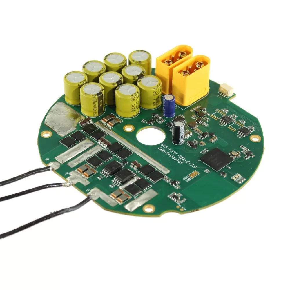
|
Connector |
Function |
Position |
|
CN10 / CN4 |
Power input + CAN bus, 4P |
TOP |
|
CN9 |
RS485, 3P |
TOP |
|
CN6 |
Motor temperature NTC, 2P |
TOP |
|
U / V / W |
Three-phase motor pads |
TOP |
|
CN1 |
Encoder A, 6P |
BOT |
|
CN2 |
Encoder B, 6P |
BOT |
|
CN3 |
Combined encoder, 10P FPC |
BOT |
|
J1 |
JTAG download |
— |
CN10 / CN4 power and CAN, 4-pin: 1 VP+ supply positive, 2 GND supply negative, 3 CAN_L bus low, 4 CAN_H bus high. Large contacts carry power, small contacts carry CAN 2.0.
CN9 RS485, 3-pin: 1 485A to host A (+), 2 485B to host B (−), 3 GND signal ground.
CN1 / CN2 encoder A and B, 6-pin each: 1 +5 V encoder supply, 2 GND, 3 CLK+, 4 CLK−, 5 DATA−, 6 DATA+. Pins 7 and 8 are fixed ground pins.
CN6 temperature, 2-pin: 1 IN_TEMP to the motor NTC lead, 2 GND return.
1. Check that the drive and the joint are coaxial before fastening. The ring format tolerates misalignment poorly and radial load on the board is the usual cause of a cracked joint.
2. Route power and sensor cables separately to keep switching noise out of the encoder lines.
3. Fit a 120 Ω termination resistor at the end of the CAN bus when more than one node is on the line.
4. Power down before any wiring change. Cable colours follow the encoder manufacturer's own datasheet, not this page.
5. On first power-on, configure the parameters for the joint and run the automatic phase detection routine before commanding motion.
6. Keep the centre bore clear of metallic debris. Anything ferromagnetic loose inside a joint will eventually reach the encoder.
Each board is packed in an anti-static bag, cushioned with pearl foam, and boxed individually before carton packing, so the capacitor bank and the connectors are not loaded in transit. Bulk orders are packed in double-wall cartons with separators.
We ship samples and small orders by express, urgent volume by air, and full orders by sea. Export documentation is prepared for each shipment.
A: We are a manufacturer. Board layout, power stage and firmware are developed in house, which is why Customized current, voltage, communication and feedback combinations are possible on the same ring format.
A: Yes. The model code exists for that reason: peak current, maximum voltage and interface are separate segments. Tell us the joint envelope and the bus, and we will confirm the model.
A: [10 pcs]
A: [4 weeks]
A: Yes. Configuration software is provided with the drive for parameter setting and phase detection.
A: [12 month]
A: Yes. The last segment of the model code selects X for non-resolver encoders or R for resolver feedback.
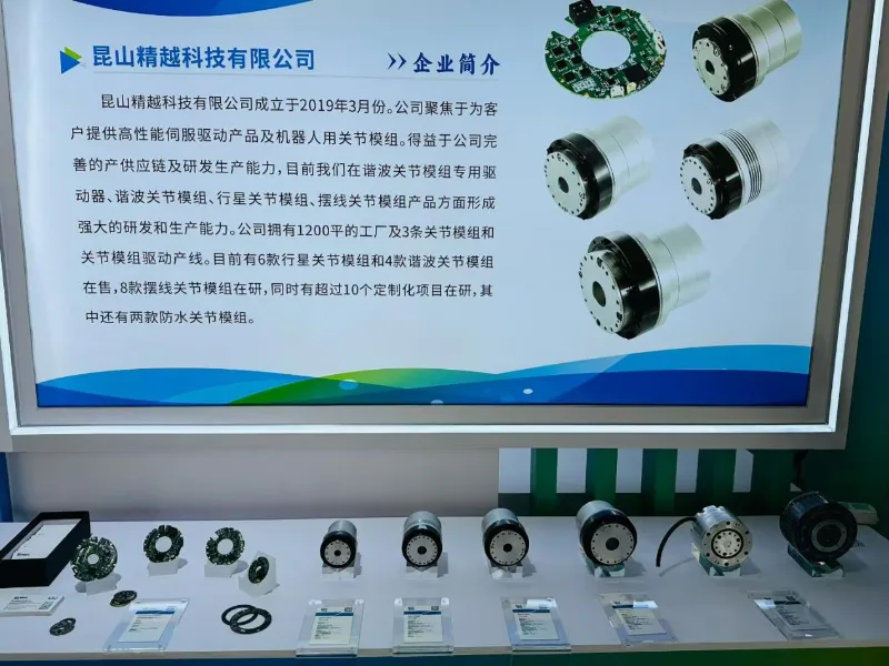
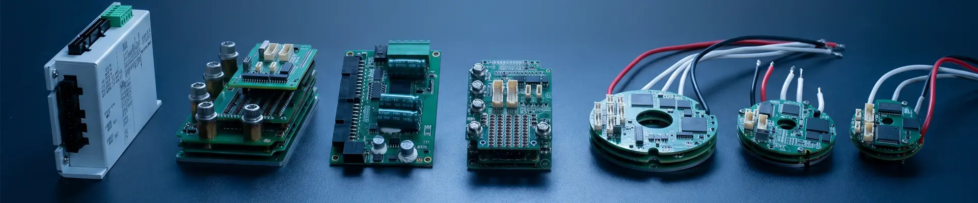
SEA MOTION builds servo drives for robot joints, not general-purpose drives relabelled for the market. The ring format, the dual encoder front end and the field weakening strategy were all developed against joint applications, where the drive has to fit inside the moving part and still hold torque at zero speed. The product line covers ring PCB joint drives, integrated servo motors and matched encoder feedback, so a joint can be sourced from one supplier with one set of interface definitions.
Send the joint drawing, the bus voltage and the encoder you plan to use. We will come back with the model code, the mounting stack-up and a sample schedule.
Address
403 4F Office Building Robot Industry Park No.232 Yuanfeng Road National High Tech Park Kunshan Suzhou Jiangsu China
Tel